Wake and shake (WS) is used to establish commutation in drives with the following types of feedback:
When controlling a brushless DC (BLDC) motor, you must know the electrical position of the motor shaft. Without absolute position data, it is impossible for the drive to know which sequence of coils to energize to produce motion. Absolute feedback devices
You can configure WS after your motor has been connected to the AKD according to the AKD Installation Manual. The WS procedure is initiated automatically when both the hardware and software enable signals become logic high.
Before attempting to enable the drive, the drive must be compensated for the motor and the AKD servo loops must be stable.
Compensation values for many rotary motors are included in a database already loaded into the drive.
An unstable system will not function properly during or after the WS process.
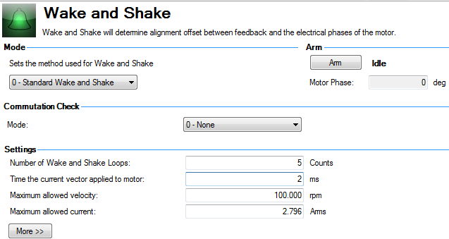
Use the default Wake and Shake view to configure your system:
Click Arm to set WS to start at the next drive enable (WS.ARM ). This area also shows the current status of the wake and shake process. See WS.STATE for a detailed explanation of the possible states.
WS.ARM is not restricted to any feedback type.
Select the type of commutation check to execute after Wake and Shake finds a new commutation angle.
0 - None: No Commutation Check
If No Commutation Check is selected, neither passive nor active commutations checks will be executed.
1 - Active: (default)
In the default Active Commutation Check mode, AKD will make a short torqueTorque is the tendency of a force to rotate an object about an axis. Just as a force is a push or a pull, a torque can be thought of as a twist move after an angle has been selected. If the motor fails to move in the expected direction, a fault will be generated.
2 - Passive:
In the Passive Commutation Check mode, AKD will monitor torque commands and acceleration values for 10 revolutions after Wake and Shake has completed. During this time, a fault will be generated if unexpected motion is detected, such as if commanded torque and acceleration are in opposition directions. Note that this fault may also be reported if the motor experiences a large torque disturbance lasting longer than WS.CHECKT.
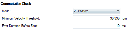
Minimum Velocity Threshold: sets the value which must be exceeded to activate commutation monitering.
Error Duration Before Fault: sets the amount of time a commutation error must be present before an error is thrown.
To configure additional WS settings, click More at the bottom of the default view to display the following
options:
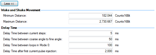
Use these boxes to set values for the maximum (WS.DISTMAX ) and minimum (WS.DISTMIN ) movement required for finding commutation.
Delay time is the time that elapses when switching different current vectors. Use these boxes to set specific time delays for current steps(WS.TDELAY1 ),coarse to fine angle (WS.TDELAY2 ) and time between loops in mode 0 (WS.TDELAY3 ).
Operation with Motor Brake
An amplifier with a motor brake operates the WS procedure similar to an amplifier without a brake. All precautions and behavioral descriptions above also apply in this case. It is important to note that the brake is automatically applied (motor brake, not holding brake) after the WS process is complete. The brake may cause unexpected movement if the DRV.OPMODE used prior to WS does not retain position. If a force component is present parallel to the track on a linear motor (gravity, load, etc.), or tangential on a rotary motor, the motor may move from the startup position after WS completes and the brake is applied.
If the application requires that the startup position be retained, have the controller system ready to take control immediately after WS is complete. One way to set this control is to have the drive in DRV.OPMODE 1 (digital velocity) or DRV.OPMODE 2 (position mode) on power-up. This precaution keeps the motor stationary after enable.
End of Travel Limits
If anything restricts the motion of the motor, a commutation fault can occur. Examples of situations that may result in faults include the following:
Large Load Inertia or High Friction System
Systems with a large load mismatch may need more current than the default setting for correct commutation. Begin with the default value for WS.IMAX and gradually increase or decrease as needed. If adjusting WS.IMAX does not result in a successful commutation, the width of the search pulse can be increased by increasing WS.T.
WS is performed upon enable in order to establish a valid value for MOTOR.PHASE at startup. MOTOR.PHASE is used to calculate electrical phase. With absolute feedback devices, MOTOR.PHASE is a fixed offset between absolute mechanical position and the electrical position. With incremental devices, position is accumulated relative to an initial MOTOR.PHASE. However, at startup, MOTOR.PHASE is invalid since the initial position is random, thus the requirement for the WS process.
WS is a two-step process:
The amplitude of the current pulses in this process equals WS.IMAX. The drive repeats these two steps for a user-specified number of times (WS.NUMLOOPS) to produce a more accurate estimate of the electrical phase.
The drive normally indicates warning F478n478 before WS is initiated and successful. If WS fails, the commutation is not valid and the drive indicates one of the following faults:
The following suggestions will help you achieve successful commutation:
| Problem | Possible Cause | Remedy |
|---|---|---|
|
Excessive Movement |
|
|
|
Insufficient Movement |
|
|
|
Excessive Movement |
|
|
|
Insufficient Movement |
|
|
|
U, V, or W Phase Missing Fault |
Intermittent or broken motor connection. |
Check connections to motor phases. |
|
Commutation Not Initialized Fault |
Wake and Shake is required but WS procedure has previously been canceled (WS.DISARM) or has failed. |
Correct errors and rerun WS procedure. |
|
Other |
|
|
Related Parameters
|
Stay Connected with Kollmorgen       
|
Copyright © 2015 Kollmorgen™ |

|